the wanna-be "kotatsu" table
First week and project of the new quarter, the topic - Wood working but with an industrial machine and a sheet of 8” x 4” in dimension and 3/4” in thickness of wood
My design fit on the whole piece with leftover space, Maybe my next project will be a Kentucky rifle that shoots rubber bands cause why not
My design and process I usually want something useful that I’m going to use, so I made a small table, but I based it on Japanese furniture specifically a kotatsu and a coffee table, so a mix of both would be my dream table


CAD/Issues
I started with a blender mesh idea to give my brain enough to copy what I made, then I sketched it, - yes it was in that order


My original design was based on a 12” x 12” table but - It needed to have short legs but enough clearance to slide my legs under with space ~3in to slide junk or something (this wouldn’t have happened since the distance under was way too far)
Tools that do automatic work generally work better with round corners than sharp edges - 3D printers, CNC machines, and the Carvera work better with rounded corners rather than sharp edges because they can cut through in one motion rather than stop, adjust then continue, this also makes this process faster but my design didn't have this because I like squares - but if you do ignore this - my results were left with somewhat rough corners

The software wasn’t too complicated, but it looked ancient - but I got massive help from Aureil, he told me "Add sidebars," it needs dog bones". And he littlerly set up the machine beforehand plus tabs manually. So Thank you again :3
Also converting the measurements into inches for big projects helps I was able to interchange to make those "dogbones" which I did by using the half line of the circle
Tabs are something you could insert if you are using a "real real" CAD program specifically for CNC machines, Onshape did not have the feature yet, but tabs hold the object like a PCB which needs tape on the under, So it doesn't fly when the section is cut.
the results
I don’t have the “during/cutting process” since I was busy and worried it’ll go wrong, But I have an “after”


After a couple of minutes I carried it to the stairs, finally got onto the train and then the bus, got a bunch of weird stares, and finally set it up. The distance between the bars needs to be longer not because I measured wrong but because I measured from the wrong location, instead of the distance between it should’ve been the distance it ended other than that it’s a complete full, ~30” x 32” x ~14” "wanna-be kotatsu"
Silicon gyroid
Honestly I need more time for this process it's so complicated but I have the main idea.
After bouncing ideas and found myself enjoying the design of the animal crossing gyroid, I chose the funny little tree things got a reference image, and designed it
Process...
I designed in blender because I pray for those who design models that are more than 100 polygons in CAD software, turned my blender mesh into an STL. THEN I TRIED to put it onto my preferred CAD software Onshape but it doesn't like bad models, so then I went back to FreeCAD and have a negative mold of it, but I still need to convert it to a CAM file, but something I didn't mention was that it keeps crashing so first design it so it doesn't CRASH or know how sensitive the software is before then
A possible fix is how using fewer polygons helps but the design will be less pretty but more optimal for rendering since we want a real shape It will be rougher and harder which causes an issue for removal or pouring too

Final....
I am working on it, but not focusing on it too much if anything I'll just leave the file here
Colab Machine - The Purple Parrots
Update 1: This is the brainstorming section since we have 4 extra minds so I'll try to update
Update 2: We decided to make a "push through the board", where it's also a marble run, but so far we decided to use ender3 old parts using the motor and pulley system and a 3d printed cage around each unique corner hopefully, my design id hopefully an eye-popping piece with a figure jumping or something
We are pushing this back for this week (this was during Native App)
Update 3: It has been rough honestly, some parts are not working in our favor the shell/frame (my part) wasn't working well with the physical parts, so yeah here's my part and my contribution, before we pivoted to make a "type-writer pen plotter idea"
So what I saw it needed, so i was very back heavy with all the components so the logical thing to do is to revese the eight forward so I made fins that should balance the entire thing like a pyriamd base

CAD STUFF


Communication and Webservers
the plan
So My original idea was to have 2 communicating devices of the same, then it was too closely related to a walkie-talkie, which I didn't like, so then I decided to switch the plan to just one device, and it be able to communicate through a web server then it'll read the message vise versa, but the other end will be a phone so it'll be 10x easier
actaul plan
I Originally was considering making a PCB for it then it wasn't the best decision since I'm fixing the "pick-up" V2 PCB, so breadboard was used instead, but all the parts could be used in case I'll CAD later in a small fashionable piece

grabbed some basic wires and buttons with an electronic microphone, a speaker that is comically small ~4mm, and an ESP32, plugged it all in, looked at the ESP32 devkit v4 reference image with the GPIO pins, and input some test code, set up the wifi/port, set up the serial monitor and...
minor setup
But before I answer I want to explain the other things I wrote in so I got a voice RSS, got the API connected to the esp32 for it to truly speak properly and not just beep like a bad smoke detector, honestly a lot of googling and double checking to see if it worked.

the real problem...
OKAY NOW, I can say that it worked technically, it got words and was able to send things but the main problem is that I didn't get an amp so the speaker was WAAAAAY TO QUIET AND IT WAS DISPLAYING THE DATA FROM THE MICROPHONE, WHICH MEANS IT WASNT TRACKING THE ACTUAL WORDS...LIKE YOU WOULD EXPECT FROM A MICROPHONE BUT THATS NOT HOW IT WORKS, THATS SEPARATE SOFTWARE THING, WHICH I DONT KNOW BUT IT WORKS HALFWAY
BUT THE IRL has/had an aux plug so I'm going to see if I could implement that into the breadbaord
React Native : Making an app
This is react native stuff, which I'm scared of, (this is before the crash course of react and connecting a backend)
I want to design this app based on my other project with the ESP32, so it uses that interface instead of just the browser making it more accessible which is something I want to keep consistent, and open to the public
I had issues trying to get react working, I had npm, npx, and node everything updated i had expo installed, but I barely got it running I have edited some parts and I plan to animate more stuff

I was "told" I could use HTML notation somewhere but that was a lie somewhat since it is similar and acts like it but it's a different framework to what I originally thought and there is a way to use HTML notation like "
" instead but it just depends on how you do the layout
Here me editing the code after days of trying to make it work, but I will add a backend and make it functional after I make it look pretty

Make sure to clear cache and make sure you have all the dependencies and everything is updated or get ready for a lot of resets of the program or actual laptop or machine - mine did this - idk why maybe because my laptop specs or because I tried this before or just because its a lot not sure entirely why - but be patience
So I've decided I hate designing and hate how long some processes take realistically but something I'll do again, very cool skill to know and improve on
issues with just using my brain
Below we have 1 error of many- my philosophy is just to jump into it but my problem is that I do not do any prior research and rely on my future self to learn it later and so far that has been a pain
I wanted this to turn off and off my bot because might as well but that's WAY harder so I flipped to using another idea of typing something and making a pin out of that and having an app instead of a web server to display anything

Here is how my site looks now, I hate it still and some tried the animation frames which is the most fun part but I've resulted into simpler is easier

Here is actual proof I made a backend and connected to it and not just make an ugly front end


how to replicate
LOOK IT UP, DO RESEARCH AND DOUBLE CHECK - LMAO CAUSE FROM SCRATCH NOBODY KNOWS BUT STUDY UP, but the point is that if I could do it anyone can - good luck to all
But when using spare parts make sure it's what you know what it is because I had a screen that had SVG and SDA instead of IC2 even though an SVG and SDA screen needs more than 4 pins I put IC2 code and it works?? so make sure you know the product
honestly using the template and changing simple things like the color and adding custom images are the best ways to change things I just used old templates and customized them to my needs
Bepis Trap Phone
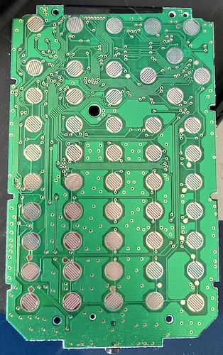
This week, from Dr. Ramsays Treaures back from his trip from China, Assigned with Leah, we discested the insides of the Alibaba Bepis phone, which is surprisingly compact and practical - a TLDR of it had 3 slots 2 for sims and for storage, mediocre screen, tiny quiet speakers and microphones and very poorly made buttons on top
these buttons arent the fancy kind which have the special metal contacter within the button since its seperate pieces


heres an example
I've opened and fixed many devices from Nintendo consoles to Texas ti calculators to dental floss pickers, so I have quite a bit of experience in opening stuff I shouldn't be
Some of the parts were easily identified and some parts were more common sense, but some were impossible 1 because neither of us knows Mandarin or the "real name" of the chips

The process to do this is to - assume and Google - There were a lot of loose parts which could be from us destroying it with screwdrivers and ripping parts or that's how it was made which isn't completely insane but there was a wire we ASSUMED to be an antenna but, strangely, it didn't look like a real antenna I've seen
The position and components are key to assuming what the parts do such as a lot of resistors probably mean it something to do with the battery disruption or the USB controlling

There was framing and shields around to keep it all together and the shields mean that the parts are sensitive and are hidden for a purpose which we assume is the screen parts to make sure all the layers are working even though it 2 main parts and 2 frameparts

I did find a lead with the manufacturer of what the phone came from and some extra parts like alternatives of their products and I even sent an email to them in Google Translate Mandarin - so far no response
The important cool parts?
MT6261D
This is the only guaranteed - which can be described, as a low-end phone chip made in 2014 and surprising specs, everything you need for a tiny poorly made nugget, Bluetooth 3.0 and 4mb of ram

there was a small 5mm speaker and 2mm mircophone and a impressive tiny screen
the reason for 4 parts is the protective cover glass (outermost layer),a transparent adhesive layer, and an LCD panel with a backlight, which includes the liquid crystal layer, color filter layer, and polarizer layers and next is the cable i choowed on


The other parts are not able to be traced
m2019t403 and sn8810hs2343 and 197101
These parts are for the data and sim card stuff and memory - the parts of the screen - I THINK idk honestly but it is something related since everything else was kinda their part and the traces didn't lead anywhere specific just general areas
The Pickup V2
A better stronger better and more optimized version of the v1 that will actaully work intentally
this comes with an an imporved shell and loading system compared to the v1 - It'll have a "drop in" system and the only issue I see is clogs which can be solved if you shake or detach the loading part to the PCB motor part
this also comes with a usable PCB that makes sense and logic like instead of a dial its buttons, below I have mt PCB Kicad schematic which was revised by Dr. Ramsay- So i assume itll work


heres my Makera Cam and Carvera Controller configuration and some specs to know - Choose PCB instead of allumininm, the thickness of the PCB to know how deep it goes is ~2mm which is good enough and the actaul traces are 0.055mm or 0.55mm - my reason is because thats what Matthew had on his site and hes smart

