For this week, I decided to work torwards my final project steadily. I went with a LCD1602 as an output device (will later upgrade to a OLED display) and a potentiometer input as a first step to more complex input devices.
This is the first go through with a breadboard which doesn't look quite right, but I took it as a win.
With this base, I stepped it up ever so slightly and added 2 LEDs, a ball tilt sensor (to approximate my acceleromter module), a button, and my some Arduino code for a basic pomodoro timer functionality.
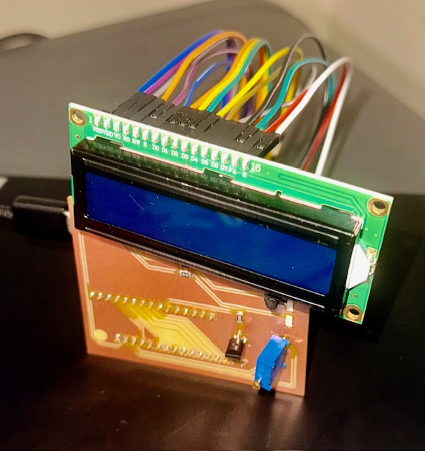
Feeling good about this idea, I decided to mill out a custom board which was looking bright until I plugged it in. My first mistake, I forgot that female headers means I mount the LCD and ESP32 (that have male headers) onto the back, so my PCB layout was messed up and I had to wire it up manual which induces some user error which I am very prone to. Second, I may have drawn my traces wrong or I wired it up wrong (both highly likely). When the whole thing is wired up, nothing works. When I unplug 5V, my LCD screen works, but my LEDs don't. When I plug in 5V, my LEDS work, so that was weird and I called it a night.
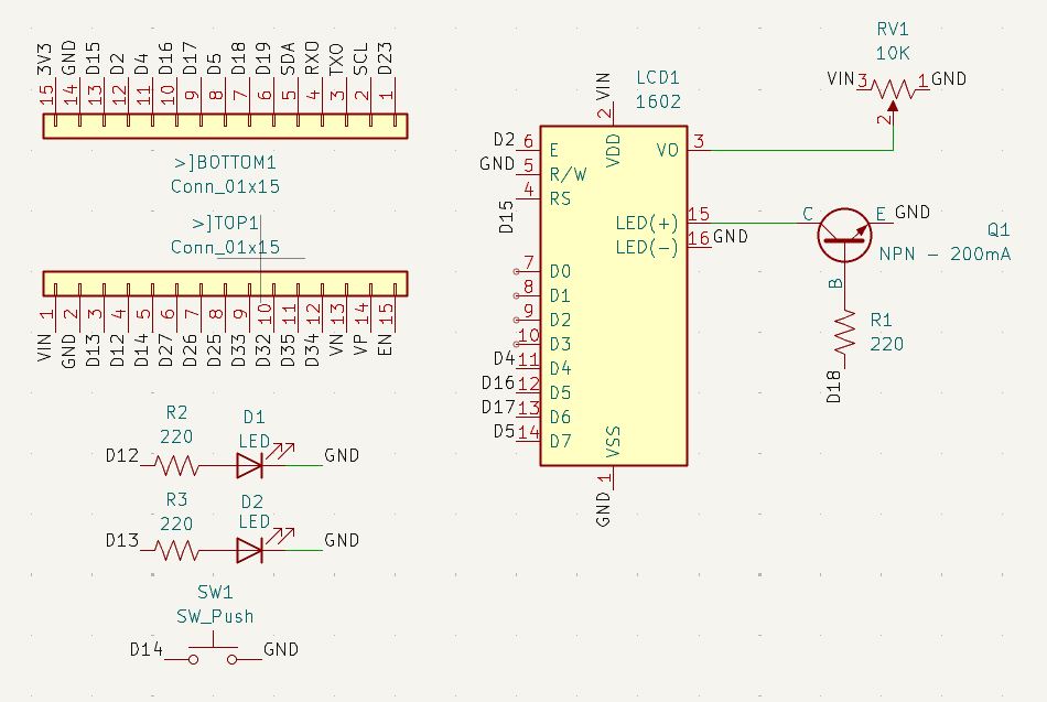
Trying to fix my custom PCB, I decided to redo the PCB and schematic layout and add a transistor to be able to switch off my LCD screen.
Another failure. Dang.
It just won't turn on when I plug it in. I'll have to look at my schematic and PCB design again, but I am sure its good.