This week was not great. Mostly because what could've went wrong did go wrong, and then I had a lot less time than I thought, so I was scrambling to get a finished product.
Basics of Electricity
This section is gonna be my understanding of electricity, so I may get it wrong, but I need this to reference in the future I guess. My first impression of voltage, current, and resistance was that it was unintuitive and it was gonna be gonna be something I just need to accept for the way it was. I didn't want to do that though.
Apparently, Ohm's Law is the holy grail equation and foundation to everything.

            V = RI

The equation was explained to me like this: V is directly proportional to I, and R act as a constant that determines that relationship. Which I like.
This was easy to understand though. What I needed was an analogy that explain the flow of electricity because the idea of voltage (and ground), current, and resistance didn't add up to how I understood their relationship. I stumbled upon a video called An Intuitive Approach for Understanding Electricity by AlphaPhoenix which was indredibly insightful and easy for a newbie to follow.
The first explanation to why voltage and ground are the way they are can be explained like this:
Let's say you had a wire that was filled with electrons and positively charge nuclei.
If we had all the electrons packed into one side of the wire. Like a pile of pebbles that get pushed up to one side, there would be a ramp-like shape. This is voltage, this is the pressure that pushes electrons because electrons don't like being forced together. The height of the ramp could then be described as the electrical potential difference, kind of like potential energy, but it is more akin to height in that analogy.
Because the other end is now depleted of electrons, that other end is now positively charged. Electrons don't like being forced togehter so they shoot out to the other side, this is like how potential energy gets transformed into kinetic energy. In the end, the electrical potential difference equalizes causing the voltage to be 0 volts. This is what ground is.
Two more things on stuff that doesn't make sense.
Circuits built in a series have voltage drops caused by each component throughout the series which is explained by Kirchoffs Voltage Law. What didn't make sense was why current remains constant despite resistors causing electrons to slow down. That doesn't make sense.
How I was guided through this is that speed is different from rate. So yes, the electrons may slow down inside a resistor or even speed up from the bouncing, but the amount of electrons flowing into the resistor is the same coming out, and the amount of electrons being pushed is the equal to the amount being pulled (Kirchoffs Current Law). The "friction" inside the resistor means voltage is needed to push the electron at a constant rate causing that voltage drop and energy (heat) to be released.
Intuitively, when I thought about electricity flow as water flowing, you'd think that the resistor placement would matter, but it doesn't. Ohm's Law is a global rule, so the magnitude of I, V, and R are affected throughout the whole circuit. It's best to think of a resistor as something that limits amount of current that flows throughout the whole circuit. Which goes back to how current is constant, and that current affects that constant' magnitude. Oh wait, that's Ohm's Law!
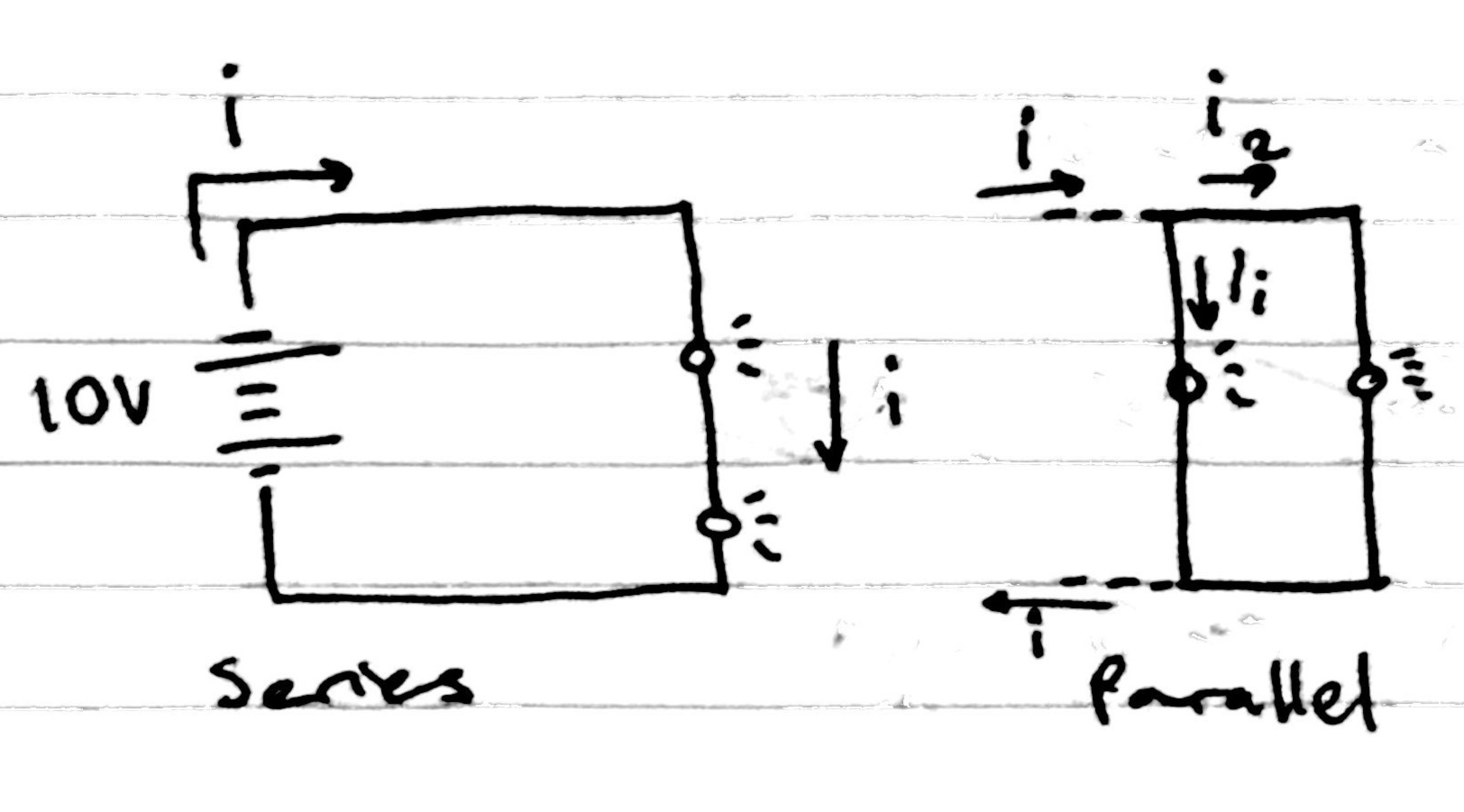
Last thing, parallel is different from series, in that instead of voltage changing, current changes. This makes sense in a waterpipe analogy too. Water flowing through a straight pipe is constant, but water flowing through a pipe with a junction causes the flow to split.
In consistence with what I know, series work they way they do because voltage has to not split to make Ohm's Law and Kirchoff's Current Law true. If voltage is the potential difference and both LEDs have the same points (top wire and bottom wire), their voltages have to be equal.
Hopefully my meandering explainations serve someone well, or maybe I'm on my own on this.
Update (5 days later): Turns out I am overcomplicating things.
Not really voltage, that was unintuitive, but the other stuff. So V = IR is the whole grail because I can just derive why series and parallel work the way they do.
            Series:
                I = I1 = I2 = I3 ... (KCL)
                V = V1 + V2 + V3 ...

                V = I(R1 + R2 + R3 ...)
                R = R1 + R2 + R3 ...

            Parallel:
                I = I1 + I2 + I3 ... (KCL)
                V = V1 = V2 = V3 ...

                I = V/(R1 + R2 + R3 ...)
                1/R = 1/(R1 + R2 + R3 ...)
PCB Shield
The deliverable for this week was a custom PCB shield with atleast a resistor and a LED. I did just that because I am new to this world.
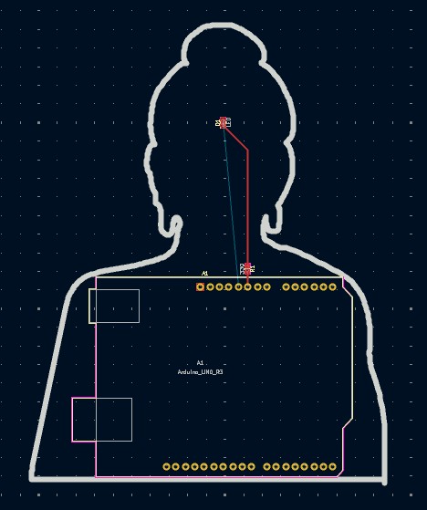
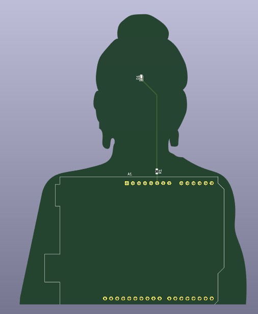

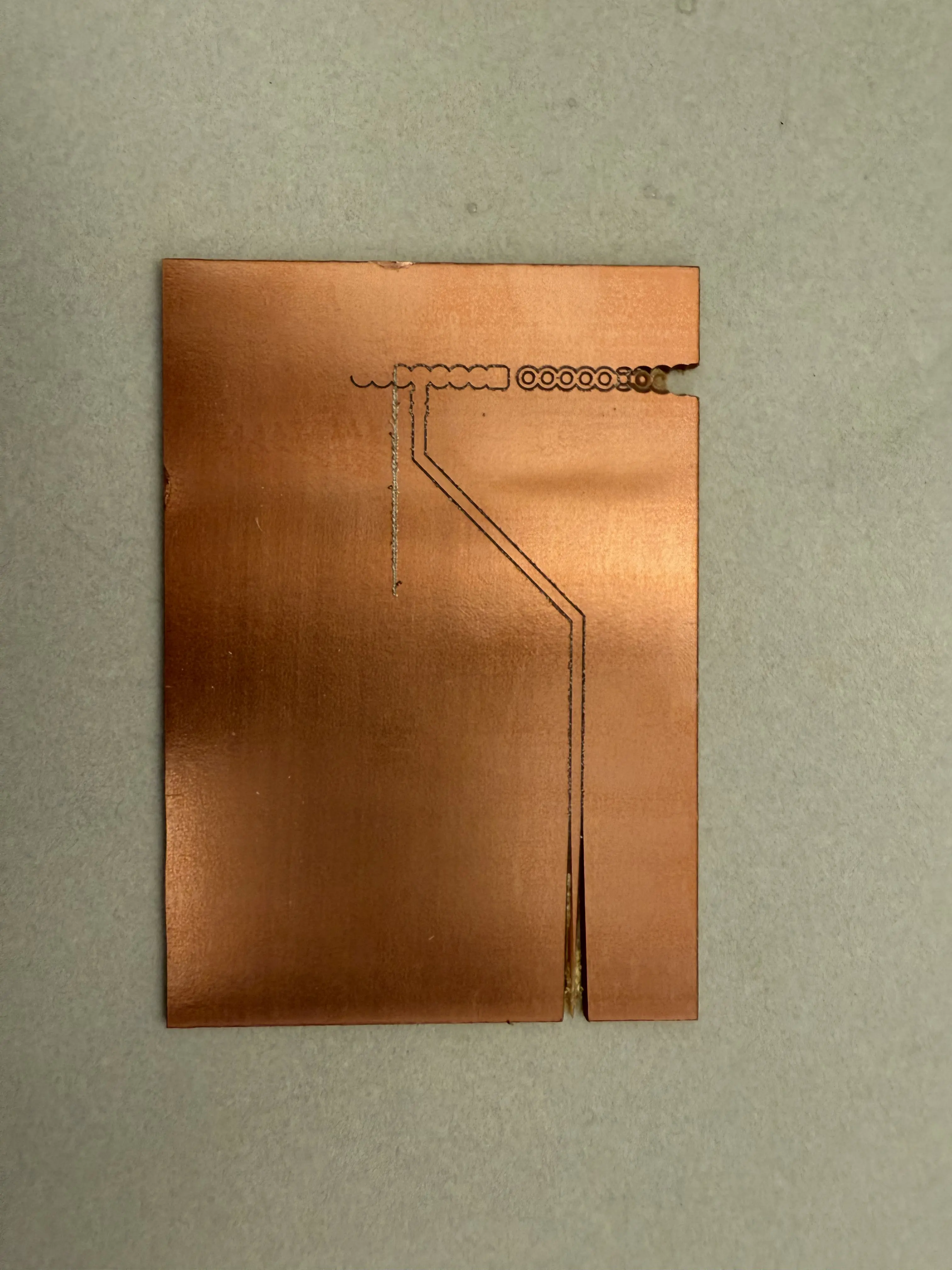
Things didn't go as planned, as my shield was too big compared to the material and some part of my configuration was wrong leading to bad cuts and engraving. Here is the failed attempt:
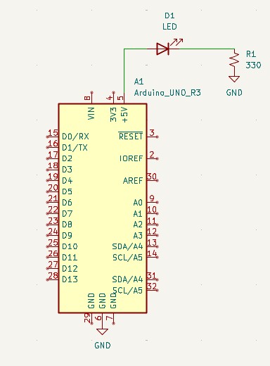
In turn, I had to make a new design that was simpler and something that could minimize risk and deliver a finished product.
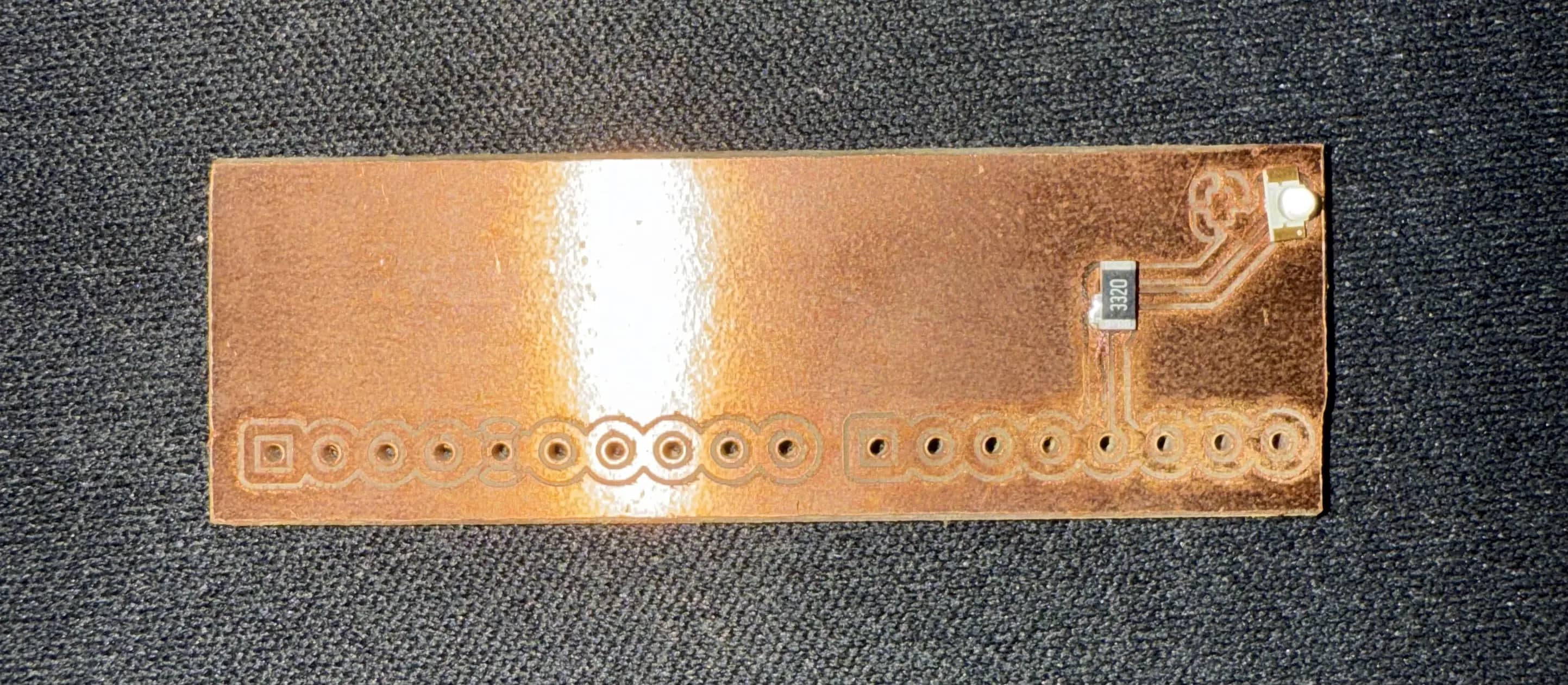
However, I didn't take into account my competency in electronics so I fricking soldered the LED in the wrong direction and made the footprint for a 0603 instead of a 1206 component, so I have to redo this one. This is gonna be something I come back to, and I will get right.