Week 2 of Machine Week was ... hard. Lots of late nights in the IRL led to a partial success. While the robot CAN hit the puck, it is plagued with tensioning issues that prevent actual gameplay.
DESIGN/ASSEMBLY:
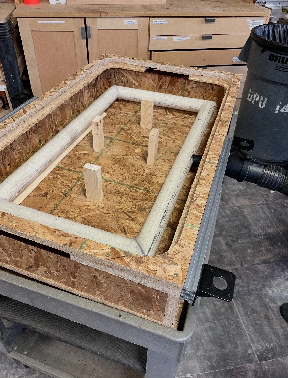
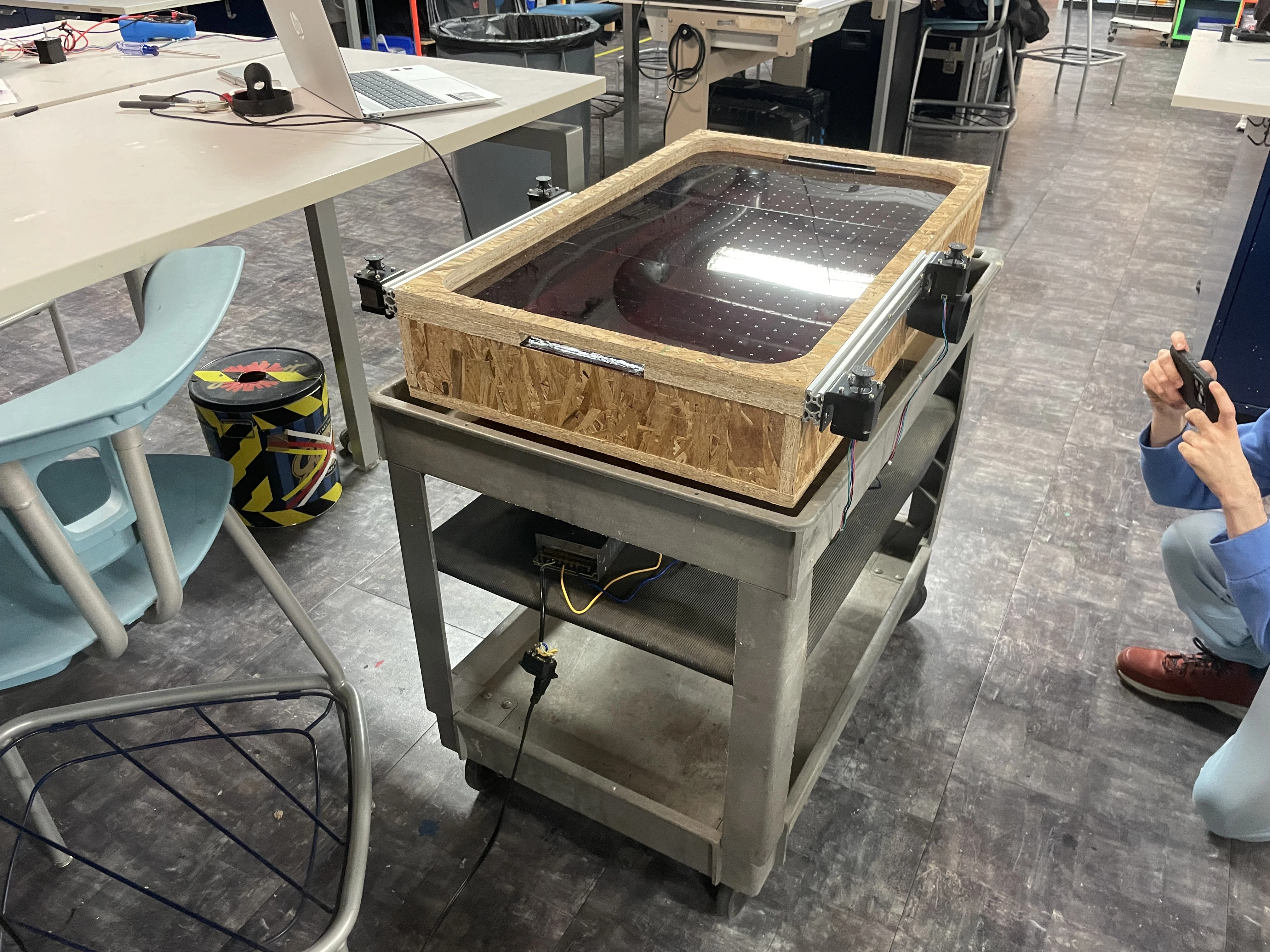
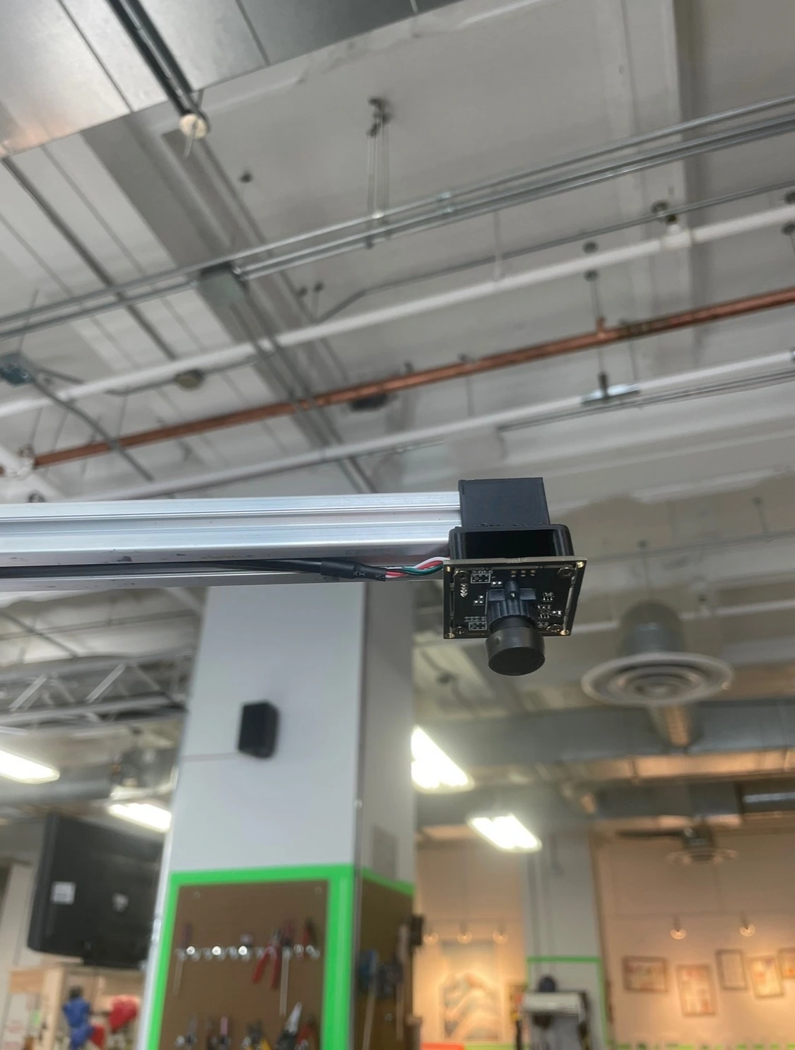
This is the section I was in charge of. I had the main body and surface already cut and assembled from week 1. The next steps were to cut and install supports to prevent the thin acrylic from drooping. After that, I screwed 2040 extruded aluminum to the sides for mounting the motors and camera tower. The stepper brackets had to be modified to fit the hardware on hand. To finalize the box, I 3d printed an adapter to connect the vacuum to the table, and a tube to bring the air into a circuit of PVC with drilled holes to create turbulence. This was very effective in providing even air pressure across the table. I 3d printed a bracket to mount the camera to more extruded aluminum, holding it 30 inches above the table. The final step was to 3d print spools for the 250lbs test fishing line to connect the motors to the mallet.
HARDWARE:
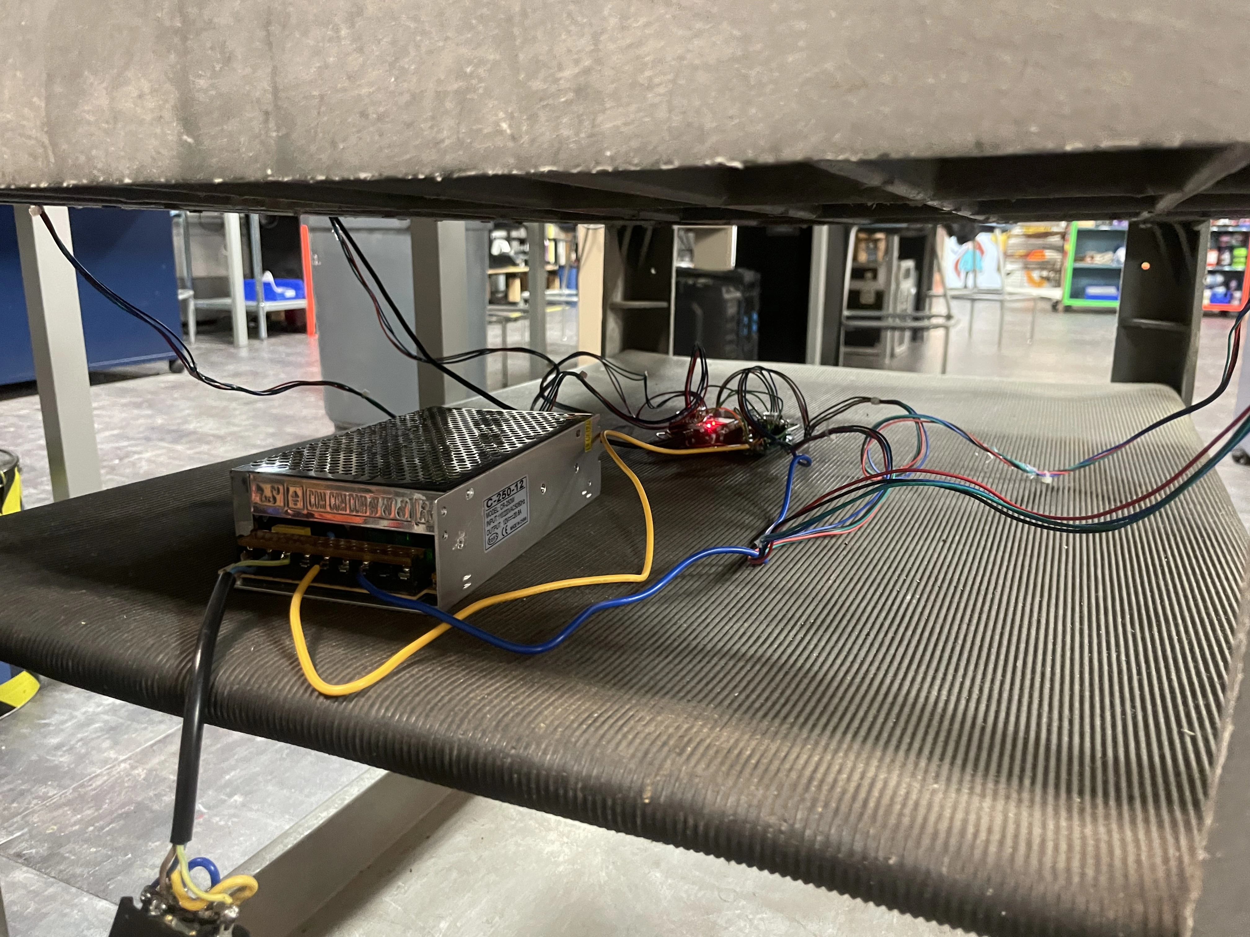
This was Alex's portion. Unfortunately, the CNC shield we bought only supported 3 drivers. To mitigate this, Alex used a protoboard to connect each driver directly to our Arduino Uno. This whole system was attached to a power supply, and installed on the shelf directly below the hockey table box.
SOFTWARE:
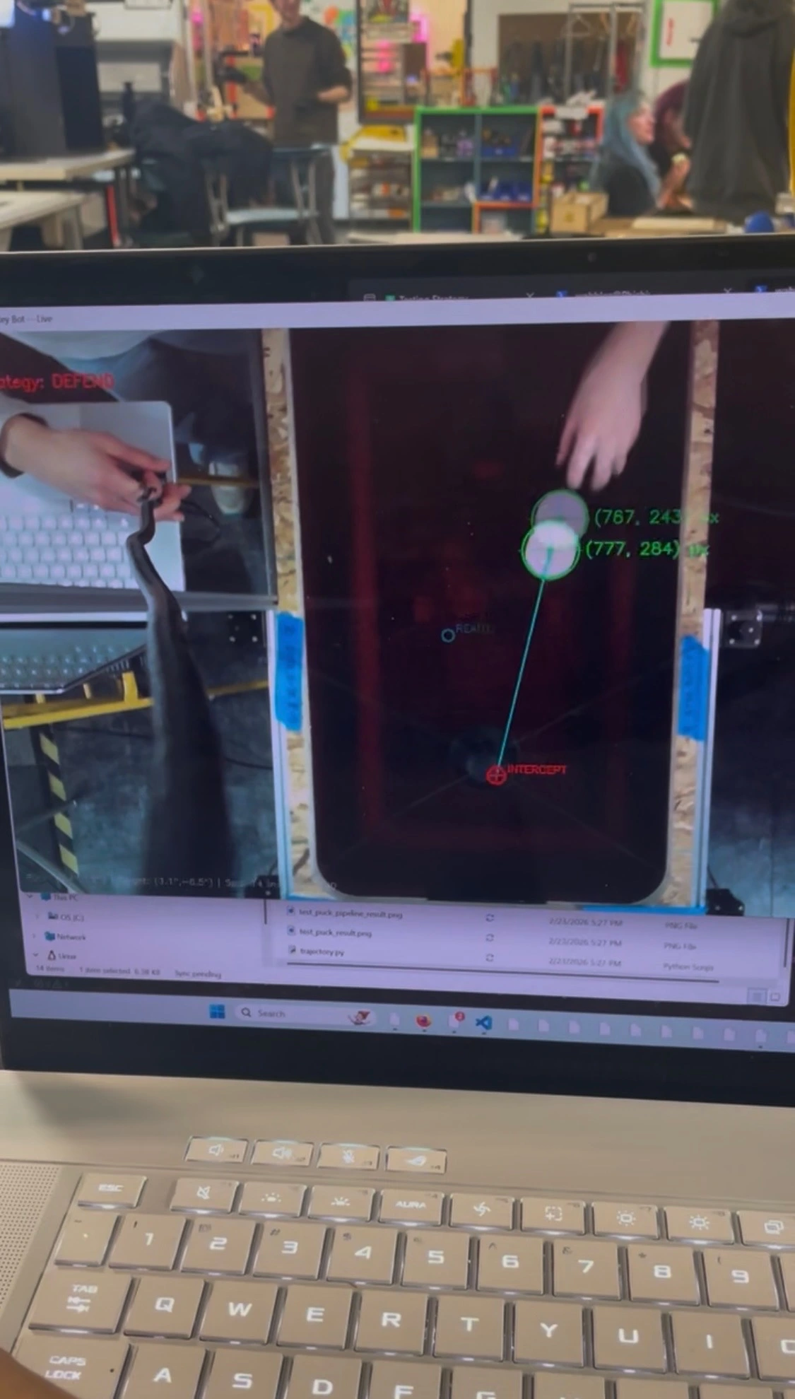
The puck I made was laser cut white acrylic, meaning a camera can easily distinguish it from its surroundings. Luke did a great job at coding a system that applied path tracking to the puck, and estimated where the mallet should move. This is translated to the 4 stepper motors, moving the mallet into the correct position.